Upgrading Your Tunnel Radio System: What to Know
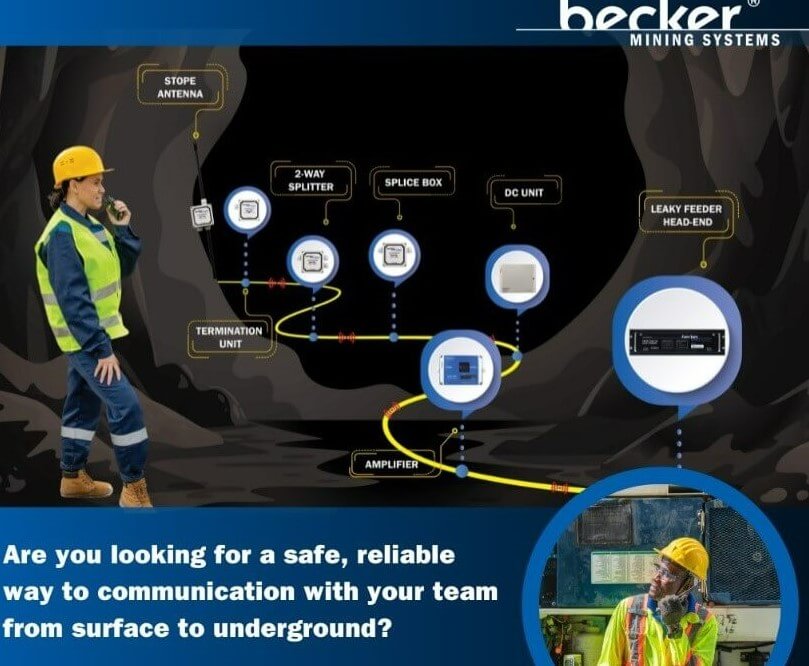
A tunnel radio system has to do something ordinary wireless networks struggle with: maintain dependable communication through long, confined spaces surrounded by rock, concrete, steel, equipment, and changing underground conditions.
That makes an upgrade more involved than replacing an old radio or installing a stronger amplifier. The entire communication path matters—from the base equipment and backbone to the radiating cable, antennas, amplifiers, power supply, monitoring tools, and emergency functions.
At Becker/SMC, we understand how closely underground communications are tied to safe, productive operations. Our work includes electrical, control, and communication systems for demanding underground environments, including leaky feeder technology that helps extend radio coverage where conventional signals have difficulty reaching.
If an existing system is developing dead zones, relying on obsolete parts, or becoming difficult to maintain, an upgrade can improve more than audio quality. It can make the communication network easier to monitor, expand, troubleshoot, and support over the long term.
Key Takeaways
- A tunnel radio system should be evaluated as a complete network rather than as a collection of individual radios and amplifiers.
- Leaky feeder cable and distributed antennas can provide continuous RF coverage through areas where normal radio signals are heavily attenuated.
- Fiber optic backbones can make large or multi-section systems easier to expand while reducing dependence on long chains of RF repeaters.
- Automatic gain control and remote diagnostics can reduce manual adjustment and help maintenance teams identify communication problems sooner.
- Dead zones, repeated component failures, discontinued hardware, and unavailable software support are strong signs that an older system deserves a full technical review.
- Emergency features such as Voice Break-In may be important in certain road-tunnel applications because they allow operators to interrupt normal broadcasts with safety instructions.
What Does a Modern Tunnel Radio System Include?
A modern tunnel radio system typically combines radio-frequency distribution equipment with a physical communication backbone designed specifically for confined environments.
One common approach is a distributed antenna system, or DAS. Instead of relying on a distant antenna to penetrate the entire tunnel, the system distributes RF signals throughout the structure.
Radiating coaxial cable—often called leaky feeder cable—is widely used for this purpose. The cable acts as both a transmission line and a distributed antenna, allowing RF energy to enter and leave the cable along its length. This creates a communication zone along the tunnel rather than depending on a signal from one distant point. NIOSH describes leaky feeder cable as a distributed antenna capable of transmitting and receiving radio signals along the underground route.
Depending on the installation, a tunnel communication network may also include:
- Base stations or radio interfaces
- Radiating coaxial cable
- Fixed antennas
- Bi-directional or in-line amplifiers
- Fiber optic links
- Power supplies and backup power
- Monitoring and diagnostic equipment
- Control-room interfaces
- Emergency communication functions
The right combination depends on the tunnel, the frequencies that must be supported, the people or systems using the network, and what the owner expects the system to do during normal operations and emergencies.
How Do You Know When a Tunnel Radio System Needs an Upgrade?
A tunnel radio system should be considered for an upgrade when reliability is declining, parts are becoming difficult to obtain, or the existing architecture can no longer support current operating requirements.
Age by itself does not necessarily mean the entire network must be replaced. A functioning system may still have useful infrastructure. The more important question is whether the network can continue to provide dependable coverage without creating an excessive maintenance burden.
Dead Zones Are Appearing or Getting Worse
Coverage problems are one of the clearest warning signs.
A dead zone can develop because of damaged cable, deteriorating connectors, amplifier problems, changes to the tunnel, new equipment, or poor signal balance. Even a system that originally provided good coverage can change as the underground environment changes.
Do not assume adding another amplifier will automatically solve the problem. Excessive gain can create its own RF problems. The cause should be identified before new equipment is added.
Repair Calls Are Becoming Routine
Older communication systems often become expensive gradually.
One amplifier fails. Then a power supply needs replacement. A connector starts causing intermittent faults. Another discontinued component has to be sourced from remaining stock.
At some point, maintenance crews spend more time keeping the existing architecture alive than improving the network.
That is often the point where a planned modernization becomes more practical than continued one-component-at-a-time repairs.
Replacement Parts Are Being Discontinued
Obsolescence can turn a manageable failure into prolonged downtime.
Watch for manufacturers discontinuing:
- Batteries
- Chargers
- Amplifiers
- Power supplies
- Interface equipment
- Control software
- Replacement circuit boards
- Firmware or software support
A component does not have to fail before it becomes a risk. If a critical part can no longer be replaced promptly, the operation is already carrying a maintenance vulnerability.
The System Cannot Be Monitored Remotely
Older systems often require technicians to physically travel through the tunnel to determine where a problem occurred.
Modern monitoring systems can make network status and diagnostic information available locally or remotely. Tunnel Radio, for example, markets its TRCentral system specifically for remote access to system performance and troubleshooting information.
The broader lesson is not that every operation needs the same monitoring platform. It is that diagnostics should be considered part of the upgrade architecture rather than an afterthought.
Should You Replace the Leaky Feeder Cable?
Not necessarily. Existing leaky feeder infrastructure should be tested before deciding whether it can remain in service.
Radiating coax remains an effective way to distribute radio signals through tunnels because it provides coverage along the route rather than at isolated antenna points.
During an upgrade assessment, examine:
- Cable condition
- Connector condition
- Signal loss
- Physical damage
- Water or corrosion exposure
- Amplifier spacing
- Coverage at branches and intersections
- Changes to tunnel geometry
- New equipment that may affect RF propagation
Sections that remain electrically and mechanically sound may still be usable. Other areas may need replacement or a redesigned antenna arrangement.
That is why a coverage survey is more useful than making decisions based only on the age of the cable.
When Does a Fiber Optic Backbone Make Sense?
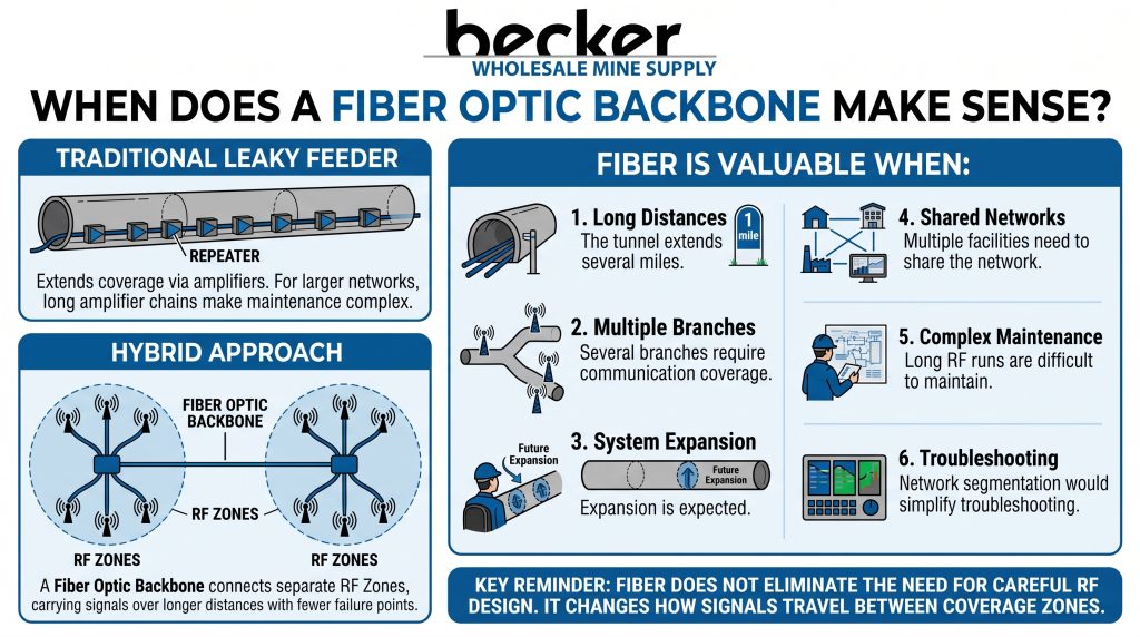
Fiber becomes especially useful when a tunnel system covers long distances, multiple sections, or several connected operating areas.
Traditional leaky feeder systems can extend radio coverage with amplifiers placed along the cable. For larger networks, however, repeatedly extending RF through long amplifier chains can make the system more complicated to maintain.
A fiber optic backbone can connect separate RF zones or sections of the leaky feeder network while carrying signals over longer distances between them.
The competitor system supplied for this article uses that hybrid approach: fiber connects larger sections of the network, while radiating cable distributes RF locally. Its published fiber system is positioned as a way to connect multiple worksites or leaky-feeder sections while reducing the number of intermediate repeaters and potential failure points.
Fiber can be particularly valuable when:
- The tunnel extends for several miles
- Several branches require communication coverage
- Expansion is expected
- Multiple facilities need to share the network
- Long RF runs are difficult to maintain
- Network segmentation would simplify troubleshooting
Fiber does not eliminate the need for careful RF design. It changes how signals travel between coverage zones.
GET IN TOUCH
In a hurry? Call us at +1-724-515-4993
Why Automatic Gain Control Matters
Automatic gain control, or AGC, allows an amplifier to adjust signal gain within its designed operating range rather than depending entirely on repeated manual tuning.
This can be useful in distributed communication networks because the signal entering an amplifier may vary with cable length, system configuration, or other RF conditions.
Modern tunnel communication equipment may include AGC to help maintain more consistent signal levels. Tunnel Radio, for example, lists automatic gain control as a feature of its distributed antenna equipment and specifies AGC on its rail voice amplifier.
AGC is not a substitute for proper system engineering. Poor cable placement, damaged components, interference, or incorrectly designed amplifier spacing still need to be corrected.
Think of AGC as a tool for maintaining a properly designed network—not a way to compensate for a poorly designed one.
Remote Monitoring Can Change How the System Is Maintained
A communication failure deep inside a tunnel creates two problems: the failure itself and the time required to locate it.
Centralized monitoring can reduce the second problem.
A modern diagnostic system may allow maintenance staff to check equipment status, identify alarms, review performance data, or narrow down a fault before someone travels underground.
For a large operation, that can change maintenance from:
“Where did the system stop working?”
to:
“Which device or section is reporting the fault?”
The exact monitoring capabilities vary by system, so confirm which components can actually report status and which faults still require field testing.
Remote access also raises cybersecurity and network-access questions. Any upgrade that connects operational communication equipment to IP networks should include an appropriate review of authentication, access control, network segmentation, and maintenance responsibilities.
Do You Need Voice Break-In?
Voice Break-In, or VBI, is mainly relevant to road-tunnel radio rebroadcast systems where operators need the ability to interrupt normal radio programming and transmit emergency instructions to tunnel users.
The World Road Association describes VBI as a system that lets tunnel operators interrupt rebroadcast radio programming and transmit emergency safety messages. Those messages may be live or prerecorded.
For a road tunnel, that can provide another channel for reaching drivers during incidents.
For mining, industrial, or railroad applications, emergency communication requirements may be different. Two-way operational radio, dispatch communication, alarms, signaling, tracking, or other systems may carry more importance than commercial broadcast interruption.
The correct question is therefore not simply, “Does the new radio system have VBI?”
It is:
“Which emergency communication functions does this particular tunnel need, and how should they integrate with the rest of the safety system?”
Do Not Upgrade Individual Components Without Looking at the Whole Network
One of the easiest mistakes is replacing the visibly outdated equipment while leaving the underlying problem untouched.
For example, a new amplifier will not permanently solve a problem caused by deteriorated radiating cable.
Likewise, new radios cannot fix poor antenna placement, damaged connectors, inadequate backbone capacity, or unreliable power.
Before specifying replacement hardware, document the complete signal path.
That assessment should include:
- Required coverage area
Identify portals, shafts, branches, work zones, equipment rooms, cross passages, and other areas requiring dependable communication. - Required frequencies and services
Determine which voice, data, dispatch, emergency, or operational systems must use the infrastructure. - Existing cable and antenna condition
Measure rather than assume. - Amplifier locations and gain requirements
Verify that spacing and signal levels still fit the current tunnel configuration. - Backbone architecture
Decide where RF distribution makes sense and where fiber could simplify longer links. - Power availability and resilience
Communication equipment is only reliable if its power source is reliable. - Monitoring requirements
Determine what operators and maintenance teams need to see remotely. - Expansion plans
A system sized only for today’s tunnel may become restrictive when the operation grows.
Plan for Maintainability, Not Just Initial Performance
A tunnel radio system can perform well on commissioning day and still become difficult to own.
Maintenance requirements deserve the same attention as RF performance.
Look at where equipment is mounted, how technicians reach it, whether diagnostic information is available remotely, how quickly components can be replaced, and whether spare parts will remain available.
Also consider documentation.
A maintainable system should have accurate records showing equipment locations, cable runs, amplifier settings, fiber paths, power sources, network connections, and test results.
Without that information, every future repair takes longer.
Upgrade in Stages When a Full Replacement Is Not Practical
Some tunnel operators cannot shut down a complete communication network for a single major replacement.
A phased upgrade may make more sense.
The sequence could involve replacing obsolete head-end equipment first, modernizing sections of the RF network, introducing fiber between major zones, adding monitoring, and replacing deteriorated cable as access becomes available.
The exact sequence depends on the existing architecture.
The important part is designing the end state before beginning the first phase. Otherwise, temporary decisions can become permanent limitations.
A staged project should still move toward one coherent communication architecture.
Test Coverage After the Upgrade
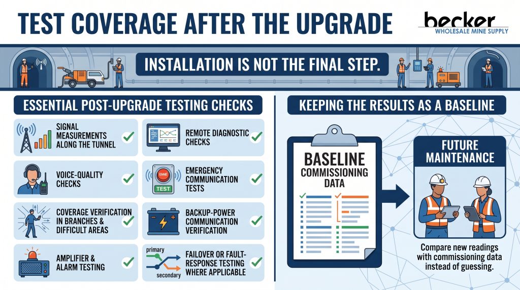
Installation is not the final step.
The upgraded tunnel radio system should be tested under real operating conditions to confirm that the design performs as intended.
Testing may include:
- Signal measurements along the tunnel
- Voice-quality checks
- Coverage verification in branches and difficult areas
- Amplifier and alarm testing
- Remote diagnostic checks
- Emergency communication tests
- Backup-power verification
- Failover or fault-response testing where applicable
Keep the results as a baseline.
Future maintenance teams can then compare new readings with the commissioning data instead of guessing whether system performance has changed.
GET IN TOUCH
In a hurry? Call us at +1-724-515-4993
Build the Upgrade Around the Tunnel, Not Around a Parts List
Every underground environment changes the communication problem.
Tunnel length, construction materials, branches, curves, equipment, available power, supported frequencies, emergency requirements, and future expansion can all affect the right design.
That is why the best tunnel radio system upgrade is rarely the one with the longest equipment list. It is the one that provides the required coverage while remaining practical to troubleshoot, maintain, and expand.
At Becker/SMC, our background spans electrical systems, underground controls, transit infrastructure, and communication technologies for demanding environments. Becker/SMC was established in 1971 and today operates from Bristol, Virginia, where we design and manufacture electrical and control equipment for mining and other industries. Our capabilities also extend into transit infrastructure and underground communication applications.
If your current communication network is becoming difficult to support, the right starting point is a system-level review. Identify what still works, where coverage is failing, which components are becoming obsolete, and what the operation will require in the years ahead.
From there, the upgrade can be engineered around the tunnel rather than around the limitations of the old system.
Talk With Becker/SMC About Underground System Requirements
An aging communication network does not always require a complete replacement, but continuing to repair obsolete equipment without examining the overall architecture can create larger reliability problems later.
We can help evaluate underground electrical and communication requirements and determine where modernization may make sense for the operation.
Contact Becker/SMC to discuss your tunnel or underground system requirements.
Frequently Asked Questions
Q: Can an existing leaky feeder system be upgraded without replacing everything?
A: Yes. Depending on cable condition, frequency requirements, coverage needs, and equipment compatibility, some existing infrastructure may be reusable. A technical survey should determine which sections remain serviceable before replacement decisions are made.
Q: Why use fiber optic cable in a tunnel radio system?
A: Fiber can connect distant RF coverage zones without extending every signal through a long series of RF amplifiers. This can improve scalability and simplify the architecture of large or multi-section networks.
Q: What is automatic gain control in a tunnel radio system?
A: Automatic gain control allows compatible amplifiers to adjust gain automatically within their operating limits to help maintain suitable RF signal levels. It can reduce some manual tuning requirements, although the overall RF network still needs to be properly engineered.
Q: What is Voice Break-In in a tunnel?
A: Voice Break-In is an emergency function used in certain road-tunnel broadcast systems. It allows the tunnel operator to interrupt normal rebroadcast radio programming and transmit emergency instructions to drivers.
Q: How often should tunnel radio coverage be tested?
A: There is no single testing interval appropriate for every tunnel. Testing should reflect the operating environment, applicable requirements, system criticality, maintenance history, and any physical changes to the tunnel. Coverage should also be checked after major repairs, modifications, or communication-system upgrades.
Products That We Offer
- VHF Leaky Feeder System
- UHF Leaky Feeder System
- SMARTSENSE®FIXED MONITOR
- RNG-500VHF Leaky Feeder Cable
- UHF Low Loss Leaky Feeder Cable
- Kenwood NX-203/303 Radios
Take control of your mining communication systems today! With Becker Wholesale Mine Supply, the leading manufacturer in the USA. Contact us now and revolutionize your mining communication systems!